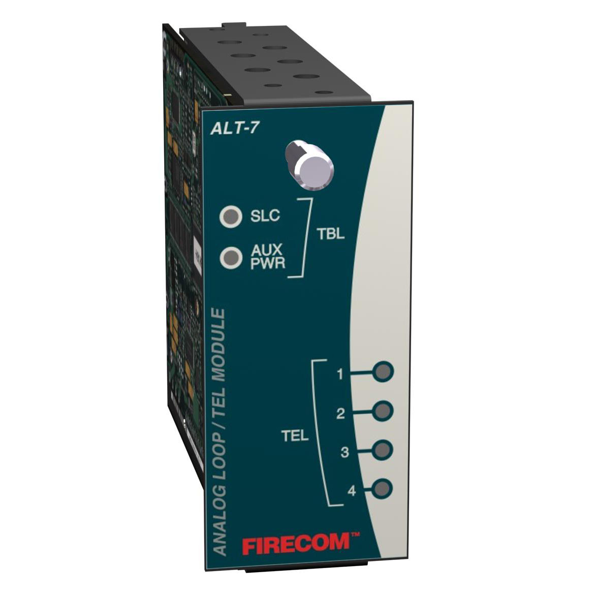
The ALT-7 Analog Loop and Telephone Module combine one analog addressable Signaling Line Circuit (SLC) and four Firefighter/Warden Telephone circuits. The SLC communicates with smoke detectors and other input and output modules over a twistedpair wire. The SLC wiring can be configured as Style 4 (Class B) or Style 6 (Class A).
Any combination of detectors and modules can be mixed on the SLC. Each detector is independently configurable to incorporate an alarm verification feature that reduces the number of "unwanted" alarms. Each detector may have a varying sensitivity setting that is based upon manual settings or changed in reaction to events or a time or weekly schedule. The ALT-7 polls each analog addressable device and reports their Alarm, Trouble, or Normal status to the COM-2 Communications Card located in the DAB-7 Motherboard of the DAN7 Cabinet. Device status is then transmitted over the riser net work wires to the Fire Command Center (FCC) and other nodes in the system. Dirty detectors can be sensed and their status is reported as a Trouble Maintenance condition. A 1.5A @ 24VDC auxiliary power output provides power for remote modules that require power in addition to the communications loop. Optional Degrade Mode programming allows input and output devices to continue to operate in the event of a failure of the microprocessor on the COM-2 card of the DAN-7.
The Firefighter/Warden Telephone circuits can be configured as 4 Style Y (Class B) circuits or 2 Style Z (Class A) circuits. Each circuit can communicate with Firefighter Phone Jacks or up to three 2wire Warden Stations. The telephone circuits are monitored and controlled by the COM-2 Communications card in the DAN-7. When a Firefighter's phone is plugged into a jack or a handset "callsin", a callin signal is transmitted to Fire Com mand Center (FCC). The operator pushes a switch on a Display Control Module at the FCC to establish a communication session between the telephone handset at the FCC and the "called-in" phone. The FCC operator can communicate with up to five simultaneous Firefighter/Warden phones.
Call progress tones are presented through the phone handset. When a phone "calls-in", a ringtone can be heard in the earpiece. If a call cannot be processed, a busy tone will be heard. Once the call is in progress, tones are removed. Activation indicators on the module indicate which circuits are in use and turned on. Upon command of the operator at the FCC, a Warden Phone or a handset plugged into a Firefighter Phone Jack can be enabled to page selected areas of the facility. A ground fault on any circuit is automatically detected, and a technician invoked ground fault isolation test helps in the identification of the circuit that is presenting the ground fault condition.
-
- Microprocessor Controlled
- Low Power Consumption
- All Wiring Power Limited
- Space Saving Design
- Analog Addressable Signaling Line Circuit (SLC)
• 126 Analog Addressable Devices
• Style 4 or Style 6 SLC Wiring
• Smoke Detector Alarm Verification
• 4 Levels of Sensitivity - Firefighter/Warden Telephone Circuits
• Style Y or Style Z Telephone Circuits
• Supports 2Wire Warden Phones & Jacks
• Active Zone Indicators


